Manager Yuan:18018037702
Manager Ma:17705182284
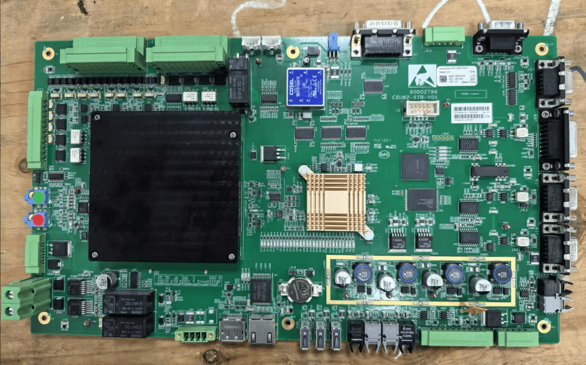
United Imaging uCT528 SIB Board
I. Basic Information Full Name: Stator Interface BoardCommon Names: Gantry SIB Board, Bracket Control Board, Gantry SIBApplicable Models: uCT528, uCT510, uCT520 (Compatible with all 5-series platforms)Installation Location: Electrical cabinet at the rear/side of the gantry, on the stator side of the slip ring. It connects to DCB, GPC, IIU and the high-voltage generator.Function: Serves as the data exchange hub, timing control and power management unit between the gantry, console and reconstruction system. II. Core Functions (Four Modules) Gantry Bus Communication (Primary Function) Transmit and receive optical and electrical signals via the slip ring; connect to the rotating-side DCB (Data Control Board) and GPC (Gantry Power Control Board). Conduct high-speed data exchange with the console and IIU (Image Reconstruction Unit), including raw detector data, operating status and fault codes. Implement exposure interlock and timing control for the high-voltage generator, X-ray tube and detector. Gantry Logic & Motion Control Control gantry rotation, tilt and locking, and feed back operating status. Process linkage signals for the movement and lifting of the patient table. Perform system self-check and report Class C error codes. Power Distribution & Monitoring Supply regulated secondary power to the on-board DCB, GPC, detector, motors and sensors. Provide overvoltage, undervoltage and overcurrent protection, temperature monitoring and fuse management. Safety Interlock Process signals for anti-collision, overtravel protection and emergency stop. Implement high-voltage safety interlock, door interlock and scanning room protection monitoring. III. Common Faults & Error Codes (uCT528) Startup Errors Error codes: C220258, C220259 (Gantry communication timeout / Handshake failure) Console prompt: "Waiting for gantry system startup, timeout after 5 minutes" Gantry Malfunction No response after power-on: No rotation or tilt, no status display, scanning unavailable. Scanning interruption: Abort during exposure, image acquisition failure, detector disconnection. Associated errors: C140000 / C14000B (Abnormal optical fiber link) Typical Causes Damage to main chip or communication FPGA on SIB board, faulty optical fiber interface, burned power module, lost firmware, broken or poorly contacted optical fibers between SIB and DCB/GPC. IV. Spare Parts & Maintenance (uCT528) Original Part Number Internal part numbers of United Imaging (vary by batch, mostly U22 series) Price Reference Brand new original board: Approximately 40,000 – 60,000 RMB Exchange part / Repair service: Approximately 25,000 – 30,000 RMB Maintenance Guidelines Prioritize inspection of optical fibers between SIB & DCB, SIB & IIU (prone to damage and contamination). Measure input and output voltages of the SIB board (±12V, ±5V, 3.3V). Re-flash SIB firmware and restore factory settings. Carry out chip-level repair for power circuits, communication interfaces and FPGA, or replace the entire board directly. V. Relationship between SIB, DCB and GPC (uCT528) SIB (Stator): Stationary side, responsible for external communication, overall control and power distribution. DCB (Rotor): Rotating side, responsible for detector data acquisition and preprocessing. GPC: Gantry power control unit, supplying power for high-voltage output and rotation drive. The three components are connected via slip ring optical fibers and control lines, forming the core control chain of the gantry. VI. Quick Troubleshooting for SIB Faults Repeated C220258 / C220259 errors on startup; SIB board is confirmed faulty after excluding optical fiber issues. Gantry shows no action after power-on, with no indicator lights lit on DCB and GPC. Console keeps displaying "Waiting for gantry startup", and the problem persists after device restart.